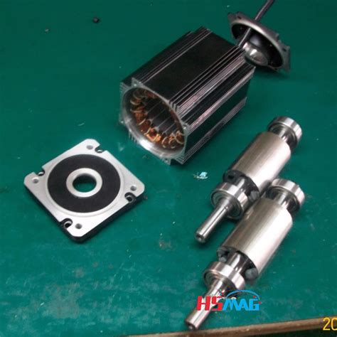
Permanent magnet rotor e1655961736623.jpeg.
Axial-flux permanent magnet (AFPM) motors have been attracting great interest due to their key advantages of high-torque density and compact structure. Concentrated windings are commonly used for AFPM motors since they significantly reduce the radial length of the end windings. This paper proposes a novel double-sided stator …
The permanent magnet motor tends to have larger step angles, 7.5° or 15°, than the variable reluctance motor. The hybrid motor typically has 200 rotor teeth and rotates at 1.8° step angles. They have high static and dynamic torque and can run at very high step rates. As a consequence they are very widely used. The geometry of one type of internal magnet motor is shown (crudely) in Figure 2. The permanent magnets are oriented so that their magnetizationis azimuthal. They are located between wedges of magnetic material (the pole pieces) in the rotor. Flux passes through these wedges, going radially at the air- gap, then azimuthally through the magnets. Apr 1, 2012 · In fact, as weâ ll explore, the major difference between PMAC and permanent magnet DC motors is that the faster a PMACâ s rotor spins, the higher back-EMF voltage is generated. Sep 2, 2020 · In the PMSG that has not been the CT reduction technique, the rotor permanent magnets (PMs) have an increasing effect on the CT since each PM has the same relative position with reference to the stator slots . The CT in each PM is in the same phase as the others, so, the harmonic component of each is added together then, CT has become higher. effects of magnet polarities [18,19], PM number [20], winding configurations[21,22], asymmetrical stator pole [23], stator/rotor combinations [24] etc., and their effects on electromagnetic characteristics have been presented. Further more, investigations of the working mechanism have demonstrated that only fundamental rotor permeance and
The actual power capacity of permanent magnet synchronous machine for electric vehicles is usually limited by rotor temperature, ... Usually, measuring the …
A magneto-structural combined dimensional and topology optimization approach for interior permanent magnet synchronous machine (IPMSM) rotor design is proposed using the solid isotropic material with penalization (SIMP) density-based topology optimization method. This method optimizes the location and dimensions of the …Feb 21, 2023 · An interior permanent magnet synchronous motor (IPMSM) with ‘VV—’ shape rotor topology structure is proposed. The established two-dimensional (2D) parameterized finite element analysis (FEA) models are used to analyze and compare the output average torque, torque density, air-gap flux density and back electromotive force (EMF) of the IPMSM with ‘V’ shape, ‘V—’ shape, ‘VV ...
Since the pole arc coefficient of the rotor permanent magnet is 0.5, according to Ref. 28, the magnetomotive force generated by the permanent magnet is equal to that generated by the adjacent FMP.an interior permanent magnet (PM) synchronous motor into a hybrid motor. This hybrid technology uses a conventional induction rotor cage to bring the motor up to its slip speed just like any traditional induction motor. Once at slip speed, the powerful interior magnets pull the rotor into true synchronous speed with the rotating magnetic field.This paper presents an analysis of torque pulsation with respect to the rotor rib shape in an interior permanent magnet motors (IPMs) and the type of magnet materials. The effects of three parameters, the angle and length of the flux barrier and the residual flux density of the PM, are studied using the response surface methodology. …In many high-speed electrical machines, centrifugal forces within the rotor can be first-order constraints on electromagnetic optimization. This can be particularly acute in interior permanent magnet (IPM) machines in which magnets are usually retained entirely by the rotor core with no additional mechanical containment. This study …
The demagnetization of rotor permanent magnet is described in terms of rotor offset caused by demagnetization, demagnetization angle, decrease of air-gap MMF at the demagnetization …
1 Introduction. Nowadays, high-speed surface-mounted permanent magnet synchronous machines (SPMSMs) are becoming more and more common due to their simple structure, high-power density and high efficiency [1-3].The rare-earth permanent magnets (PMs) are widely applied in the high-speed SPMSMs owing to their high …
2.1 Selection of Solution Variants for Analysis. In this study, an analysis of the selection of the number of stator slots to the number of magnetic poles was carried out for the structure of the Permanent Magnet Synchronous Motor (PMSM) with an external rotor, with surface mounted magnets (SPM) with a double-layer, concentrated winding …High Performance Magnets and Precision Assemblies. Arnold’s high-performance permanent magnets have a wide variety of applications, from electric motors on ships, aircraft, and motorsport cars to pump couplings, batteries, solar panels and NMR Equipment. Our diverse markets allow us to keep our technologies on the leading edge of innovation. Jun 9, 2022 · To solve the problem of tension stress caused by centrifugal force and caused by high-speed operation of permanent magnet (PM) rotor, a FeCo-based PM rotor structure model is proposed. Based on the thick-walled cylinder theory, the uniform analytical calculation formulas of strain field, displacement field, and stress field of high-speed permanent magnet rotor are derived, and the stresses of ... Mar 20, 2021 · Reluctance is a function of rotor position in a variable reluctance motor. Sequential switching (Figure below) of the stator phases moves the rotor from one position to the next. The mangetic flux seeks the path of least reluctance, the magnetic analog of electric resistance. This is an over simplified rotor and waveforms to illustrate operation. A surface-mounted permanent magnet synchronous motor (SPMSM) is an electric motor with a simple magnetic circuit design, fast responsiveness, linear torque–current characteristics, speed–voltage characteristics, and constant operating speed. SPMSMs use only magnetic torque; however, interior PMSMs (IPMSMs) have high …In order to improve the performance of synchronous motors, especially in dynamic-transient conditions, induction damper cages are usually used in the rotor structure. In this paper, a new hybrid structure of an axial-flux motor is proposed, which uses a permanent magnet (PM) rotor and an unpaired induction damper cage with …
Axial flux permanent magnet synchronous motors (AFPMSMs) have been widely used in wind-power generation, electric vehicles, aircraft, and other renewable-energy applications owing to their high power density, operating efficiency, and integrability. To facilitate comprehensive research on AFPMSM, this article reviews the developments in …Our permanent magnet rotor assembly, designed for use in brushless DC (BLDC) motors, generators, and more, are built with the highest quality materials, including neodymium …This paper is focused on the optimal design, simulation, and experimental testing of a counter-rotating double-rotor axial flux permanent magnet synchronous generator (CRDR-AFPMSG) for wind turbine applications. For the optimal design of the CRDR-AFPMSG, the particle swarm optimization algorithm to maximize efficiency and …The windings of coreless axial flux permanent-magnet machine (CAFPM) are exposed to the rotor magnetic field, where each back electromotive force (EMF) harmonic is induced not only by several ...The permanent magnet synchronous motor (PMSM) is widely used in the electric vehicle and domestic appliance industries. The structure of the PMSM motor varies depending on the permanent magnet arrangement in the rotor structure; among them, the interior permanent magnet (IPM) PMSM motors made by inserting permanent …Apr 8, 2022 · This paper proposes two structures of dual-stator permanent-magnet vernier machines (VMs) for high-torque low-speed applications. The proposed structures consist of dual-sided rotor which is sandwiched by inner and outer stators. These topologies include 22 and 46 consequent-pole magnets in the rotor and 24 and 48 stator slots for Design A and Design B, respectively. Design A is an improved ...
Oct 14, 2002 · The most important magnet layouts in rotors of hybrid permanent-magnet synchronous machines (PMSM) for electric vehicles are compared in a variety of characteristics. The effect of different rotor designs on the vehicle performance and energy consumption is evaluated for a small battery electric vehicle (BEV) for different drive cycles.
For permanent-magnet (PM) machines, only specific stator MMF harmonic, known as working harmonic, interacts with the PM field to produce continuous electromagnetic torque . Lower and higher order stator MMF spatial harmonics rotating at different speeds to the rotor, will bring about unwelcome effects, such as eddy current …In the same way in , through FEM simulations and experimental results, a simple dynamic abc model for brushless permanent magnet motors, under demagnetisation faults, is presented and validated. The strategies based on the analysis of the harmonics produced by rotor demagnetisation in the phase currents or the EMF are …Rotor (electric) The rotor is a moving component of an electromagnetic system in the electric motor, electric generator, or alternator. Its rotation is due to the interaction between the windings and magnetic fields which produces a torque around the rotor's axis. [1] In many high-speed electrical machines, centrifugal forces within the rotor can be first-order constraints on electromagnetic optimization. This can be particularly acute in interior permanent magnet (IPM) machines in which magnets are usually retained entirely by the rotor core with no additional mechanical containment. This study …Axial flux permanent magnet (AFPM) machines are good candidates for electric vehicle applications due to their high torque density, improved efficiency, and better flux distribution; thus, they are often used. A dual-rotor single-stator AFPM machine with four differently shaped permanent magnet (PM) rotors is investigated. The main aim of …Feb 21, 2023 · An interior permanent magnet synchronous motor (IPMSM) with ‘VV—’ shape rotor topology structure is proposed. The established two-dimensional (2D) parameterized finite element analysis (FEA) models are used to analyze and compare the output average torque, torque density, air-gap flux density and back electromotive force (EMF) of the IPMSM with ‘V’ shape, ‘V—’ shape, ‘VV ... The windings of coreless axial flux permanent-magnet machine (CAFPM) are exposed to the rotor magnetic field, where each back electromotive force (EMF) harmonic is induced not only by several ...Metrics. Permanent magnets constructed from metal ions and organic linkers using molecular design principles could bring transformative advances in areas such as energy conversion, transportation ...This control method can control the AC permanent magnet servo motor as a DC permanent magnet motor in a sense. According to Equations (1)–(3), the second-order dynamic equation of the position ring of the PMSM is expressed as follows: (4) { θ ˙ = ω ω ˙ = b i q + d (4) where b = 1.5 p n ψ f / J is a disturbance composed of unknown friction …
Measure Skewing Angle. MagScope software makes it easier than ever to measure the skewing angle of skewed permanent magnet rotors, enabling the detection of skewing angle deviations. The right figure shows an example of the step skew on an IPM (Interior Permanent Magnet) rotor, represented in a cross-section graph with automatic zero-crossing ...
In order to improve the performance of synchronous motors, especially in dynamic-transient conditions, induction damper cages are usually used in the rotor structure. In this paper, a new hybrid structure of an axial-flux motor is proposed, which uses a permanent magnet (PM) rotor and an unpaired induction damper cage with …
2.1 Design of Rotor Eccentric Arc and Performance Analysis. This paper takes a permanent-magnet rotor as an example. Figure 1 shows 1/8 models of a rotor without an eccentric arc design, a rotor core designed with a conventional eccentric arc, and a rotor core designed with the improved eccentric arc. The permanent magnets of the …The actual power capacity of permanent magnet synchronous machine for electric vehicles is usually limited by rotor temperature, ... Usually, measuring the temperature of the rotor permanent magnet is very difficult by equipping sensors to rotate the body directly. Some common techniques include slip rings, ...In this study, we performed an electromagnetic characteristic analysis of a permanent magnet synchronous machine considering the current waveform based on static rotor eccentricity. First, the characteristics of the back electromotive force were analyzed through the no-load analysis of the analysis model according to static rotor …The rotor overtemperature caused by losses is one of the important issues for the high-speed electrical machine. This paper focuses on the rotor loss analysis and CFD-thermal coupling evaluation for 105 kW, 36,000 r/min HSPMSM. Three types of sleeve materials as carbon-fiber, Titanium alloy, and stainless steel are introduced in this paper, …Aiming at the rotor strength problem of high speed permanent magnet synchronous motor (HSPMSM), a design method for maximum outer diameter of permanent magnet is proposed. Firstly, on the basis of mechanics of materials, the stress analytical model of HSPMSM rotor with anisotropic material is established. Then, the …Abstract. Interior permanent magnet synchronous machines (IPMSMs) with V-shaped permanent magnet (PM) rotors are widely …It should be understood that the “rotor inside” vs. “rotor outside” distinction is in fact trivial, with very few exceptions, which we will note. 2.1 Surface Magnet Machines Figure 1 shows the basic magnetic morphology of the motor with magnets mounted on the surface of the rotor and an otherwise conventional stator winding. Permanent-magnet motors can be designed to operate at synchronous speed from a supply of constant voltage and frequency. The magnets are embedded in the rotor iron, and a damper winding is placed in slots in the rotor surface to provide starting capability. Such a motor does not, however, have means of controlling the stator power factor. Magnetic micro-rotary motors are difficult to build without using magnetic materials or induction 27 because it is difficult to provide reliable sliding electrical contacts to convey currents to the rotor. One form of rotary magnetic motor is similar to that of Figures 6.2.3 and 6.2.4, except that the motor pulls into the segmented gaps a ...Synchronous motor. Miniature synchronous motor used in analog clocks. The rotor is made of permanent magnet. Small synchronous motor with integral stepdown gear from a microwave oven. A synchronous electric motor is an AC electric motor in which, at steady state, [1] the rotation of the shaft is synchronized with the frequency of the supply ... A stationary magnetic field is produced across the rotor by poles on the stator. These poles may be encircled by field coils carrying direct current, or they may contain permanent magnets. The rotor or armature consists …The rotor of the HSPMSM adopts a solid cylindrical permanent magnet rotor with the parallel magnetization of two poles. The excitation magnetic field of the permanent magnet is a standard sinusoidal magnetic field, which can provide a large magnetic potential, which is convenient for the design of large air gaps and is conducive to …
Based on the complex structural characteristics of permanent magnet-assisted synchronous reluctance motors (PMA-SynRMs), this paper proposes a multi-objective optimization design method for the motor using a composite algorithm. Firstly, the power density, electromagnetic torque, cogging torque, and torque fluctuation coefficient …Electromagnetic interaction between the rotor permanent magnet and the stator slots is quite large. (1000 N simulated value for this motor). The air-gap needs to be as small as 1 mm. Fig. 4a shows the single disc of rotor with 9° skewed permanent magnets. The machine rotors were constructed by using mild-steel.A post-assembly magnetizing fixture has been designed and successfully used to magnetize the rotor of a 100 kW high speed permanent magnet synchronous motor. The rotor is a solid cylinder with outer diameter of 80 mm and total length of 515 mm. The permanent magnet material is samarium-cobalt (Sm 2 Co 17) withInstagram:https://instagram. culverandfree pikmin 4 download code for eshop5 star nails and spawherepercent27s the cheapest place to buy gold A permanent magnet rotor assembly is a crucial component in various applications, including BLDC motors, generators, and magnetic couplings. It consists of a rotor with permanent magnets, such as neodymium magnets, mounted on it to ensure an efficient and reliable magnetic field generation. The interaction between the magnetic field … 187029blogalice dc u street A double-sided permanent magnet rotor with a single stator [2, 3] can offset the axial attraction and increase the output power at the cost of an increased weight. The double-sided permanent magnet rotor design can also reduce bearing wear and noise problem compared with a single-sided structure, which thus increases the generator … big ten basketball standings women The fundamental operation of a permanent magnet motor is like most electric motors; the outer stator holds windings of coils fed by a power source, and the rotor freely rotates based on the forces imparted by the stator coils. Many of the same basic principles for induction motors hold true for permanent magnet motors, and more information can ... Mar 16, 2015 · A post-assembly magnetizing fixture has been designed and successfully used to magnetize the rotor of a 100 kW high speed permanent magnet synchronous motor. The rotor is a solid cylinder with outer diameter of 80 mm and total length of 515 mm. The permanent magnet material is samarium-cobalt (Sm 2 Co 17) with saturation magnetizing field of 6 ... 2.1 Electrical Characteristics. The equivalent circuit of a PMDC motor is shown in Fig. 1. The supply voltage and the current are given. The circuit consists of an induced voltage (Vi) in series with an armature resistor (Rarm) and inductance (Larm). The rotation of the ux generates the induced voltage.